Assembly plans

Assembly documentation from the same model

The model that produced the take-off becomes the assembly plan. Bimetria lays out the frame or divides the walls into system elements, numbers them and draws an elevation of every wall. The order follows from the model, not from a per-square-metre factor.

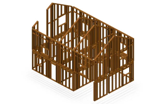
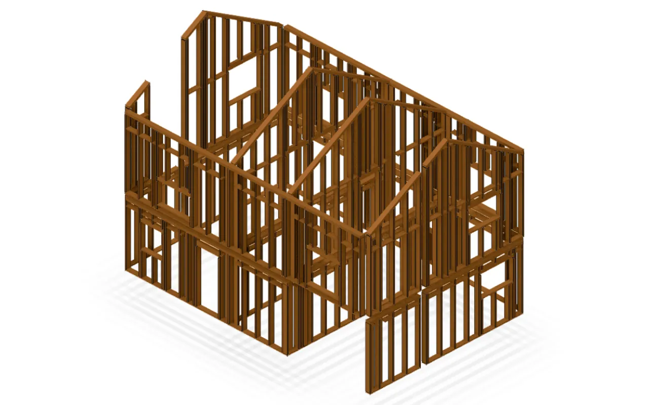
Timber frame of a detached house generated from the model

A frame laid out on the sheathing module

Studs are placed from the end of the wall at a spacing that divides the sheathing board without a remainder, so every board joint has timber behind it. Lintels, cripples, sills, top plates and blocking are created at every opening automatically.

  • Stud, joist and rafter spacing set in the project
  • A warning when the spacing doesn’t fit the board module
  • Manual changes protected by a wall lock
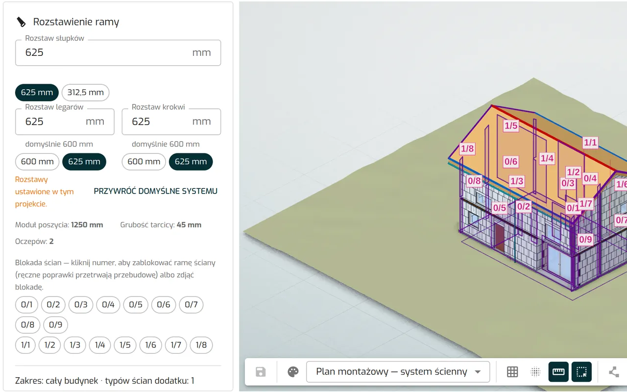
Frame layout settings and the model with numbered walls

An elevation of every wall

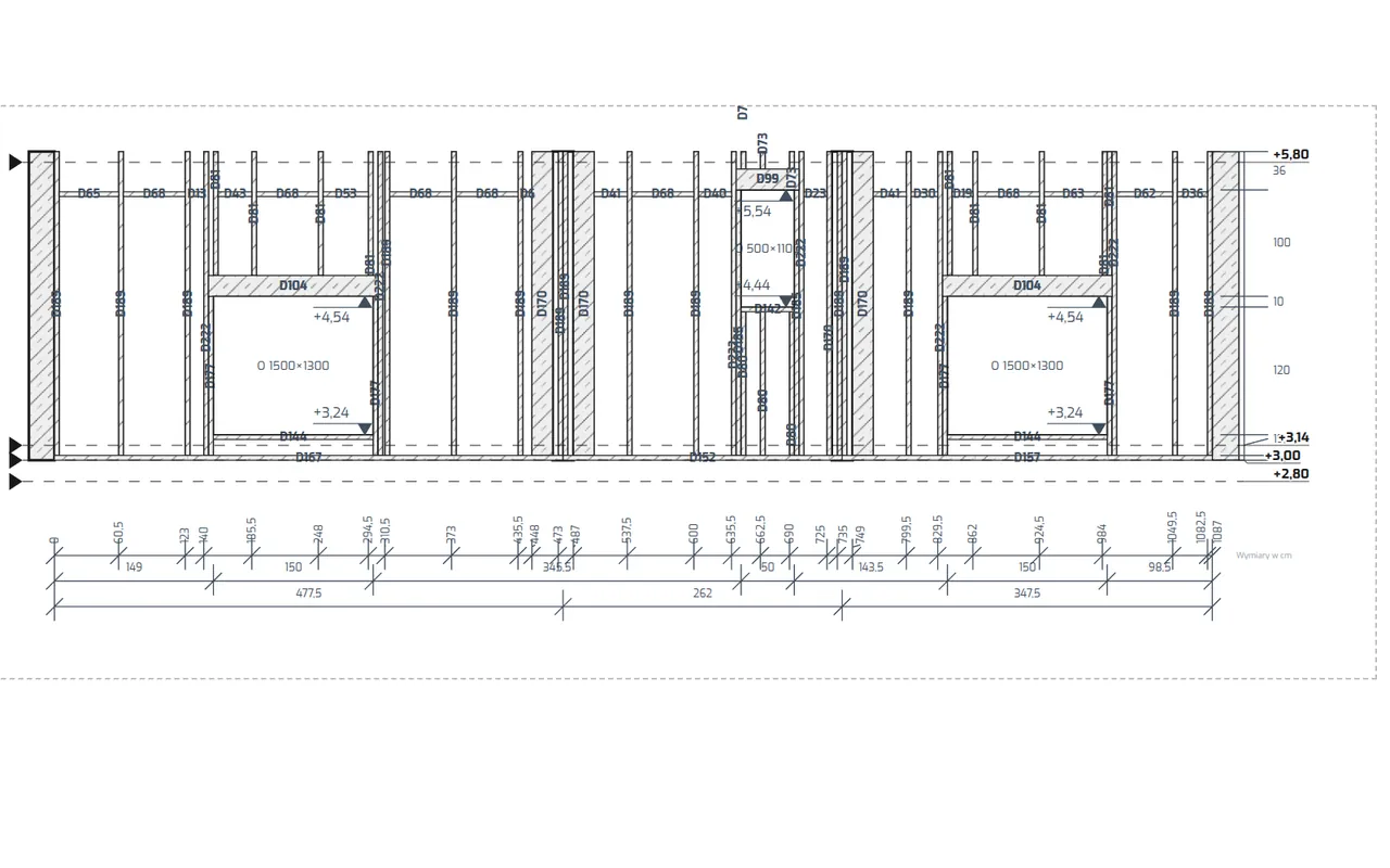
The assembly sheet shows the wall in elevation with every element labelled, dimensions and levels, plus a list of the elements in that wall. Sheets for each storey and the whole building combine into one document for the contractor.

Timber frame wall elevation with stud spacing and openings

Cutting list and timber order

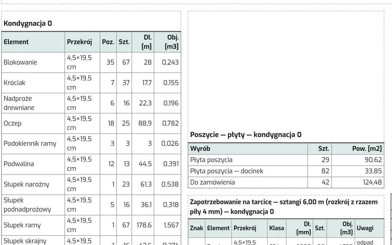
Element lists for the building, each storey and each wall, with section, length and volume. The requirement for commercial timber lengths allows for the saw kerf, and the sheathing board list separates full boards from offcuts.

Frame element list, sheathing boards and timber requirement for a storey

Systems with assembly plans

Timber frame

Frame layout, cutting lists, sheathing board list and timber requirement, in metric and imperial.

Precast concrete

Walls divided into elements with joints, shop drawings, a transport list and a crane reach check.

Large-format masonry units

Course layout with bonding, offcuts, mortar, pallets, and laying time and sequence.

Aerated concrete wall panels

Storey-height partitions, a cutting plan and pallets by delivery location.

Wood-concrete formwork blocks

Block types, offcuts, lintels and core concrete volume with pouring stages.

Beam-and-block floors

Bay numbering, beam layout, and schedules of beams, blocks and topping.

Plasterboard partitions

Profiles in commercial lengths, boards, screws, anchors and tapes.

Output

  • Assembly sheets PDF
  • Element lists XLSX and CSV
  • IFC with frame elements

Frequently asked questions

Does an assembly plan need a separate model?

No. The plan is built from the same model as the take-off. You assign a system wall type to the walls, and the layout, numbering, schedules and sheets are calculated from it.

What if I adjust the frame by hand?

You lock the adjusted wall. The next layout run skips it and keeps your changes.

Do frame elements go into the IFC file?

Yes. Studs and beams are model elements, so they go into IFC, schedules and views just like walls or slabs.

Get started

Try Bimetria on your own project

The trial lasts 7 days and needs no card. If you would rather see the app with us, write to us and we will set up a free demo.